|
The HP 9100 Project: An Exothermic Reaction
The HP 9100A desktop calculator was an ideal development project for Barney Oliver’s fledgling HP Labs. While the HP 2116A minicomputer, being developed simultaneously, would use the most advanced electronic technologies then available (integrated circuits), the HP 9100A was targeted at a lower-cost market and could not generally afford the luxury of ICs, which were reserved for machines where size and weight came at a premium, such as ICBM’s and the backup design for the Apollo guidance computer. Instead, the HP 9100A project stretched the design team to develop new uses and applications for less expensive and less power-hungry technologies such as discrete transistors, diode gates, and CRT displays.
So many technology-stretching ideas came into play from so many people during the design of the HP 9100A that Barney Oliver described the project as an exothermic reaction: a reaction that starts automatically and generates heat just from the mixing of the reacting ingredients. The main ingredients involved in the HP 9100A project included Jack Volder’s CORDIC algorithm for calculating trigonometric functions and J. E. Meggitt’s algorithms for pseudo division and pseudo multiplication, brought to HP via Volder’s and Malcolm Macmillan’s calculator design; Tom Osborne’s VLIW (very long instruction word) floating-point processor design, which resulted in a fast, low-power floating-point calculator; a printed-circuit based, inductive read-only memory developed by HP’s Chuck Near and Arnie Bergh; Chung Tung’s adaptation of minicomputer core memory to the limited storage needs of a desktop calculator; highly nested VLIW programming by Dave Cochran and Tony Lukes; and finally Roy Ozaki’s and Don Aupperle’s futuristic industrial styling that won the HP 9100A some cameo appearances in various movies. All of these people and more contributed new ideas to the rapid development of the HP 9100A.
(To see Tom Osborne’s first-hand account of this story, click here.)
CORDIC and the Hustler
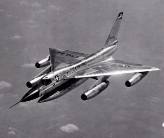
In 1956, aerospace manufacturer Convair in Fort Worth (a division of General Dynamics) was developing the world’s first supersonic bomber for the US Air Force. Although it would have a very short service life (it would be supplanted by much faster ICBM’s in the early 1960s), the delta-winged Convair B-58 Hustler bomber would stretch the envelope on a number of aeronautical and electronic technologies. (The B-58 also starred in the 1964 movie “Fail Safe.”) Most important to the story of the HP 9100A development, Convair was interested in improving the B-58’s navigation technology, which was based on analog electromechanical resolvers (rotary variable transformers), a technology developed for World War II bombers. Convair wanted the B-58’s navigation system to be far more accurate than the analog aircraft navigation computers of the day. Digital computations could produce the needed accuracy but digital computers of the mid 1950s that would fit inside of an aircraft were slow and crude at best and certainly couldn’t muster the calculation abilities needed to make the required trigonometric calculations for real-time, global navigation using the slow series-expansion trigonometric algorithms or the memory-intensive table-lookup routines of the day.
Jack Volder, a researcher at Convair’s aeroelectronics department, tackled this problem and developed a method he dubbed CORDIC (COordinate Rotation DIgital Computer) for calculating trigonometric functions using only adds and shifts (significantly, CORDIC computations do not require a multiplier, which consumes many gates). Bit shifting and simple addition are two sorts of calculations that simple digital circuits can easily perform. Volder used his 1946 edition of the CRC Handbook of Chemistry and Physics as his inspiration. Had he not developed the CORDIC algorithm, Volder believes that the work to replace the existing analog resolvers would have been abandoned.
The resulting CORDIC algorithm made transcendental calculations practical for early, simple digital computers. Volder first published his CORDIC algorithm in an internal Convair report in 1956 but it did not garner much enthusiasm within Convair or the Air Force, at least initially.
Finally, late in 1958, Volder got permission to publish his work on CORDIC in a paper that appeared in the 1959 Proceedings of the Western Joint Computer Conference. The IRE reprinted this paper in its Transactions on Electronic Computing that same year. These publications seem to have done the trick because the Air Force authorized Convair to build a prototype digital navigation computer, called CORDIC I, which was completed in 1960. That prototype was sufficiently successful and the Air Force authorized the development of a production computer, called CORDIC II, which was completed in 1962.
However, Jack Volder left Convair even before the CORDIC I prototype had been completed. During the early 1960s, Volder teamed up with a physicist named Malcolm Macmillan, who lived in southern California. Macmillan and Volder put the CORDIC algorithms to work computing trigonometric functions in a fixed-point prototype calculator named “Athena.” Macmillian demonstrated Athena to HP (probably to Bill Hewlett) in June, 1965.
Oliver and Stoft saw the Athena demonstration and were impressed with the elegant CORDIC algorithm. However, they viewed Athena’s fixed-point hardware as a “big kluge” (the worst sort of engineering epithet) and knew from experience that the hardware aproach taken by Volder and Macmillan was already outdated by the time Athena was built. Athena was large (Oliver described it as being the size of two beehives), balky (it took two days of debugging to successfully demonstrate the machine at HP after lugging it up from southern California), and relatively slow (Athena took more than a second to calculate a transcendental function, about as fast as a good engineer could perform the same calculation on a slide rule). However, the use of the CORDIC algorithm for a calculator was brilliant. By mentally applying a few math concepts and transformations, Oliver and Stoft realized that the CORDIC algorithm could be used to calculate all transcendental functions, not just the trigonometric ones implemented in the Athena prototype.
The Second Element
Oliver was fired up by Macmillan’s visit to HP with Athena. However, he knew that he needed someone with a better grasp of digital design to make the idea a practical reality in a production product. An engineer named Tony Lukes who worked for Oliver at the time recommended his friend, Tom Osborne, as a likely candidate. Lukes had worked with Osborne at SCM and had been impressed with Osborne’s digital-design skills. He suggested that Osborne was the right person to develop hardware to implement Macmillan’s and Volder’s concept for a scientific calculator. Oliver asked Lukes to bring Osborne in for a visit.
Osborne brought more than himself to the meeting. He brought his prototype calculator, the Green Machine—a 4-function, floating-point calculator prototype. When he visited HP, his calculator design had been rejected by IBM and about 30 other high-tech companies for various reasons including Osborne’s unconventional design approach and complete lack of a technical reputation. (He’d only gotten his MSEE two years earlier in 1963.) Oliver and Stoft recognized that the fusion of Athena and the Green Machine would result in a world-beating scientific calculator, one that HP’s existing test and measurement customers were sure to love.
How did Oliver and Stoft know? They used the same marketing technique that served HP well from its founding in 1939 to about 1990: next-bench market research. Briefly, next-bench market research means taking an idea to the engineer at the next bench. If he (all HP engineers were “he” back then) liked it, then it was sure to succeed. Both Oliver and Stoft liked Osborne’s ideas for a fast desktop calculator. They liked them even more when they realized they could combine Osborne’s hardware approach and Volder’s CORDIC algorithms to create a practical scientific calculator. Even better, Bill Hewlett liked the idea.
Oliver initiated the HP 9100A project in late 1965, which resulted in a working prototype a little more than a year later. Logically, Osborne might have become head of the calculator project but he didn’t wish to join HP as an employee. Osborne had shown his independent streak (Oliver said, “He had a kind of free spirit about him.”) when he quit his job at SCM to design his own calculator rather than develop Stan Frankel’s design, which he’d judged lacking. Instead of becoming an HP employee, Osborne became a paid consultant to HP and remained so for many years during which he consulted on many development projects. Osborne designed almost all of the HP 9100’s circuitry, except for the power supply and the magnetic-card reader. He also designed the sense circuits for Chuck Near’s printed-circuit ROM, which he says was the most difficult design he’s ever done.
Section leader Dick Monnier took charge of the HP 9100A project early in 1966. Monnier had been project leader on several HP sampling oscilloscope projects and a TV waveform monitor. He had a BSEE from the University of California at Berkeley and an MSEE from Stanford. Monnier’s prior experience doesn’t indicate a deep knowledge of digital computing products, but this lack experience merely underscores HP’s traditional confidence in the basic skills of the engineers it hired. Up until at least the 1980s, HP believed that any engineer it hired could undertake just about any engineering project: analog design, digital design, IC design, software programming, production engineering, component design, etc. After all, Bill Hewlett was an engineer’s engineer and the same was expected of all HP’s engineers.
Thanks for the memory
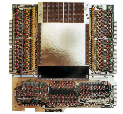
Osborne’s VLIW processor design required a 64-bit-wide read-only memory (ROM). Although the HP 9100A’s processor was actually a microprogrammed state machine and didn’t run software in the conventional sense, state-machine design can employ a control ROM to direct the machine’s operations during each state, to test branch conditions, and to specify a next state. Osborne determined that the HP 9100A would, at a minimum, need a 32-kbit ROM, organized as 512 64-bit words. The HP 9100A could have used more ROM capacity, but even 32 kbits was well beyond the state of the art for 1965-era electronics. In fact, it was completely beyond the reach of the integrated-circuit technology in 1965, which was barely able to pattern 50 devices (transistors, diodes, and resistors) on one chip; forget about 32,768 bits of IC memory.
Chuck Near’s prototype 64-bit ROM was woefully undersized for the job, so Osborne began to scale it up. Integrated-circuit technology of the day was hopelessly crude so Near had elected to use a different technology based on photolithography—multilayer printed circuitry (pc boards)—which was much farther down the manufacturing learning curve. Even so, pc-board manufacturing was just barely able to do the job in 1965. HP’s pc-board shop could not build the ROM to Osborne’s specifications at first. Osborne needed lithographic features about one third the size of HP’s best circuit-board imaging capabilities to date. Gradually, the pc-board shop learned how to pattern the ROM’s memory array.
While HP’s circuit-board shop worked on imaging the ROM bit patterns, Osborne worked on the circuitry for the ROM’s sense amps. The sense lines in the center of the ROM board produced sufficient signal so that the sense amps worked. However, because of fringe electrical effects at the board’s edges, the sense lines at the edges of the ROM board did not produce sufficient signal to operate reliably with Osborne’s initial sense-amp design. Osborne continued to refine his sense-amp design and was able to eke yet another operational bit from the ROM every two months or so. Slowly, Osborne brought the full ROM to life.
The ROM would prove to be the most complex logic assembly in the HP 9100. As a backup, Osborne built a diode-based ROM board for his first HP 9100 prototype, like the ROM he’d built for his original machine in 1964, but that ROM design would have required thousands of diodes and would have made the calculator prohibitively expensive to produce. Fortunately, Osborne succeeded in taming the fringe effects on the ROM board and HP successfully built the pc-board ROM. (For more technical details on the HP 9100 pc-board ROM, click here.)
Weaving bits into gold: A digital Rumplestiltskin
The 32-kbit pc-board ROM was not the only ROM used in the HP 9100A. The HP 9100A processor design employed 29-bit microcode instructions but it had only 64 different instructions. Sixty four instructions can be encoded in only 6 bits (although sparse instruction-word coding is quite typical of a microcoded state-machine design because it saves decoding circuitry). To save bits in the HP 9100’s pc-board ROM, each of the 64 microcoded instruction words is represented by a value in a 6-bit field within the pc-board ROM’s 64-bit microcode word. This approach saved 23 bits per instruction word and kept the problematic circuit-board ROM’s word size to a barely manageable 64 bits. However, as a result of this bit compression, the HP 9100A needed additional circuitry to expand the microcode instruction field from 6 bits to 29. Today, we’d use a simple semiconductor ROM or a programmable-logic device to perform this expansion, but such technology was far beyond reach in 1965.
Instead, Osborne used another unusual memory device called a woven- or braided-wire (or simply “rope”) memory to perform the expansion. This “magnetic ROM” consisted of 29 ferrite cores (which look like small black donuts). A sense wire passes through each of the 29 cores and 64 drive wires pass through some cores (producing a one) and around the outside of other cores (producing a zero). A current pulse in the drive wire inductively generates all 29 bits of the microcode instruction simultaneously.
The last remaining memory in the HP 9100A was the read-write core memory used to store the values in the calculator’s registers. The HP 9100A used a 2208-bit, lithium-ferrite core memory organized as three primary registers (X, Y, and Z) and sixteen additional registers (labeled in hexadecimal as “0” through “9” and “a” through “f”). This core memory was the same sort of memory broadly used in mainframe computers and minicomputers of the day. However, the HP 9100A’s core memory was kept small to keep costs down.
Each register in the HP 9100A could hold one floating-point value (a 10-digit, signed mantissa and a 2-digit, signed exponent). Registers “0” through “9” and “a” through “d” could also hold 14 program steps each, for a total capacity of 196 program steps. (HP 9100A programming enthusiasts would quickly bump up against the calculator’s programming capacity and HP would scramble to offer more memory in the updated version of the calculator, the HP 9100B.)
Although core memory was in common use for computer-memory storage by 1965—HP was already using core memory in the HP 2116A minicomputer under development at the same time as the HP 9100A calculator—the relatively small amount of core memory needed by the HP 9100A meant that the calculator’s core-memory cost per bit was relatively high. That’s because there’s a certain amount of overhead circuitry needed for any core-memory assembly (address decoders, column drivers, and sense amps), regardless of the memory’s capacity, and that overhead circuitry sets a minimum cost for the memory. The HP 9100A really needed semiconductor memory, but HP would have to wait another generation for the IC industry to catch up to the design requirements of HP’s calculators.
The HP 9100A’s core
The random-access core memory was really the “core” of Tom Osborne’s concept for a fast calculator. Core memory’s 1.6-microsecond access time was blazingly fast compared to the delay-line memory in Stanley Frankel’s calculator design. The speed of the core memory allowed Osborne’s machine to run at a very fast 1.21 MHz (it was fast for 1965, anyway). As a result, the HP 9100A could add or subtract two floating-point numbers in 2 milliseconds, multiply two numbers in 12 milliseconds, and perform a trig computation in 280 milliseconds. These speeds made the HP 9100 ten times faster than competing electronic calculators, far exceeding the performance requirements for hand calculations (the operator can scarcely tell the difference between a 2-millisecond addition and one that takes 100 milliseconds). However, these speeds are absolutely required for a programmable calculator like the HP 9100A, which must perform many iterative computations during program execution.
The HP 9100A’s core memory was organized into registers of 6-bit words. Each register consisted of sixteen 6-bit words. Each 6-bit word held one 4-bit BCD (binary coded decimal) digit plus a sign bit or one 6-bit program step (one keycode). A BCD digit stores the numbers 0 through 9 and wastes the most significant six binary codes (hexadecimal “a” through “f”) of the 4-bit number by leaving them unused. Dave Cochran, who wrote the code for the HP 9100, used the extra two bits in each 6-bit digit as programming flags and algorithm states for intermediate calculations (such as overflow). He also employed the six “unused” BCD numbers “a” through “f” as “other” numerals, such as “f” to represent -1.
Cochran recalls that the choice of BCD or binary representation was not obvious in the early days of the HP 9100 project. Each representation had its advantages. The advantage of binary representation was that binary calculations are generally faster than BCD calculations. That’s one reason why today’s PCs use binary calculations. However, accuracy was a prime concern for the HP engineers and there are inevitable conversion errors when going from BCD to binary representations and back. Human operators always enter data in decimal notation and wish to read results in decimal notation so such conversions are unavoidable if a machine’s internal numeric representation is binary. In addition to the conversion error, BCD-to-binary and binary-to-BCD conversion routines take time, which can nullify the speed advantage of binary computation. Consequently, after much discussion, the HP engineers decided to use BCD representation in the HP 9100 calculator.
Six bits per step
An HP 9100A program step was synonymous with a keycode and the calculator had 62 keys, so each keycode required 6 bits of storage. Each calculator register could thus hold either 16 numerals or program steps, however the actual capacity as implemented in the HP 9100A was 14 BCD digits (to make one floating-point number) or 14 program steps per register. (Note: although a 6-bit-wide memory may seem quaint today, it was a standard word width in the early 1960s. For example, IBM’s early mainframe computers used 6-bit words until its System/360 shipped in 1965.)
Of the 14 BCD digits stored in an HP 9100 register, 12 were used to store the floating-point number’s mantissa and two were used to hold the floating-point number’s exponent. Each BCD digit also carried an extra bit to indicate the mantissa’s or exponent’s sign. Although the HP 9100A maintained 12 significant digits in the mantissa and performed all calculations in floating point, the least two significant digits of the mantissa were treated as guard digits and never displayed. (But if you multiplied a number by 10, you could “peek” at the two guard digits by multiplying the number by 100 to move all the digits left by two places.)
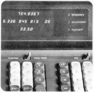
The HP 9100 calculator did have a “decimal digits” wheel that controlled the display formatting of the three numbers shown on the its display (representing the contents of the X, Y, and Z registers of the calculator’s stack). This feature allowed the operator to restrict the displayed precision to a size that was appropriate to the problem being solved. However, the calculator always performed its calculations using full-precision floating-point numbers, no matter the setting of the digits wheel.
As mentioned, the HP 9100A had three visible registers called X, Y, and Z. The values of these three registers appeared on the calculator’s 3-line CRT display. In addition to the X, Y, and Z registers, the HP 9100A also had sixteen auxiliary registers labeled “0” through “9” and “a” through “f.” Each of these auxiliary registers could also hold a floating-point number.
Alternatively, auxiliary registers 0 through 9 and a through d could store 14 program steps each, for a total of 192 program steps. Registers X, Y, Z, e, and f could only hold floating-point numbers, not program steps. With registers X, Y, and Z added to the 16 auxiliary registers, the HP 9100A had 19 user-accessible registers but the HP 9100A’s core memory implements 23 registers. The remaining four registers were not user-accessible and were used for internal storage of intermediate values and machine state. Osborne also used the extra register bits and the extra 6-bit words scattered throughout the precious core memory to encode other information needed to control and operate the calculator.
Too much static
HP introduced the HP 9100A calculator privately to a selected group of customers at the IEEE Electro show held in New York during March, 1968. The HP team brought the only five pre-production calculator prototypes in existence to the show and set them up in a hotel room. During the setup, Barney Oliver leaned over one of the open machines and his necktie dragged along the calculator’s logic board, heavily laden with diodes. Sparks of static electricity jumped from Oliver’s tie to the diodes. The machine died instantly, leaving only four HP 9100 prototypes to demonstrate.
During the Electro show, Bill Hewlett invited An Wang, founder and head of Wang Labs, to see the HP 9100. Wang Labs was the leading vendor of scientific calculators at the time and Hewlett knew that the HP 9100 was about to put a big dent in Wang’s business. An Wang looked at the HP 9100, observed its calculation speed, and left after thanking Hewlett and saying, “We had better get busy.” Eventually, Wang would file a patent-infringement suit against HP for the HP 9100’s use of logarithms in its algorithms but Dave Cochran did some research tracing the origins of the logarithm-based algorithms in question to the British mathematician Henry Briggs who lived during the 16th and 17th century, thus ending the lawsuit. There’s nothing like having 300-year-old prior art to stop a patent-infringement suit.
HP formally announced the HP 9100 to the world in the pages of the September, 1968 issue of the HP Journal. As the HP 9100A’s success in the market grew, its memory quickly became a limiting factor. HP introduced a “B” model of the calculator with double the register memory about a year after introducing the HP 9100A. Later, HP upped the HP 9100’s memory again with an external memory box called the HP 9101A (see below).
Physically mapped programming, a key per function
The HP 9100A delivered unprecedented computing power for its size. Further, it did so in a very unthreatening manner, using the guise of a scientific calculator to introduce low-cost, programmable computation to the scientific and engineering communities. It accomplished this feat by using an intuitive, physically mapped programming language: its keyboard. All the functions that the HP 9100A could perform were always in view on its 62-key keyboard so there was no need to memorize a conventional programming language like FORTRAN.
The HP 9100A’s designers physically grouped the calculator’s keys to simplify the machine’s use. There were four groups of keys: the entry and arithmetic operations group; the positioning and storage group; the coordinate conversions, extended trig, and log functions group (essentially the CORDIC group); and the programming group. An operator could use the HP 9100A as a simple calculator by only using the entry and arithmetic operations key group and one key (the double-size “up arrow” or “enter” key) from the immediately adjacent positioning and storage group. Because the HP 9100A used “reverse-Polish” notation (RPN)—the first of many such HP calculators—no parenthesis keys were needed.
HP selected RPN because it simplified the design of the calculator’s state machine by forcing the operator to parse the computation before using the calculator. Because RPN requires that a complex problem be solved from the innermost set of nested parentheses outward, the human operator simplifies the problem for the calculator. In other words, because the human operator must decompose the problem, the calculator need not know how to do so. (Remember, the HP 9100 had only 512 64-bit words for programming.)
The entry and arithmetic operations key group included individual keys for the numerals “0” through “9,” the decimal point, the four simple arithmetic operators (add, subtract, multiply, and divide), square root, change sign, enter exponent, clear X (clear entry), and π (pi). Note the absence of a key for equals. RPN calculators don’t use the equals operator like algebraic calculators. To add two numbers together, you key in the first number, press the “enter” key, then key in the second number, and press the “+” key. On the HP 9100A, the “enter” key was located in the positioning and storage key group.
|
|
|
HP 9100A positioning and storage key group
Photo courtesy Hewlett-Packard Company
|
|
|
|
|
|
|
HP 9100A coordinate conversions, extended trig, and log functions key group
Photo courtesy Hewlett-Packard Company
|
|
|
|
|
|
|
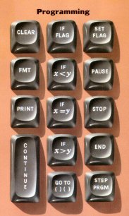
HP 9100A programming key group
Photo courtesy Hewlett-Packard Company
|
|
|
|
This second key group, positioning and storage, highlights another aspect of the HP 9100A that differentiated it from algebraic calculators. RPN calculators require that the human operator be explicitly aware of certain registers in the calculator. The three main registers in the HP 9100A are designated X, Y, and Z. Values stored in all three of these registers appear on the HP 9100A’s 3-line display during calculations.
The X register is the entry or keyboard register. When you enter a number into the calculator, it goes directly into the X register. To make room for the next number, you need to move the first number that you entered into another register (usually Y). The “enter” key moves the value in the X register into the Y register. Pressing the key for one of the simple arithmetic operations then arithmetically combines the values in the X and Y registers and places the result in the Y (the result or accumulator) register. (Note: Osborne did this to avoid infringing on any related patents that Friden might have had. The X and Y registers were both visible in the HP 9100’s 3-line display, so the destination register for the result of the computation really didn’t matter. By the time HP developed the HP 35, which had only a 1-line display, Friden was out of the game so HP changed the operation of the HP 35’s stack so that the results of arithmetic operations went into the visible X register instead of the invisible Y register.)
The HP 9100’s Z register provides temporary, visible storage for more complex calculations. The X, Y, and Z registers constitute the RPN register “stack.” When HP developed other generations of RPN calculators such as the HP 35, it added a fourth register called the T register for additional temporary storage. However the HP 9100A had only a 3-register stack.
Origin of the “gazinta” operator
The remaining keys in the positioning and storage key group were used to move values among registers. Roll up and down keys moved values up and down in the entire stack. An interchange key swapped the values held in the X and Y registers. Two “right arrow” keys copied values stored in the X or Y registers into one of the HP 9100A’s auxiliary storage registers (“0” through “9” and “a” through “f”). These right-arrow keys quickly became known as “goesinto” or “gazinta” keys because pressing one caused a value to “go into” a storage register. (The “gazinta” operation would be a building-block feature of the non-RPN HP 9825A desktop calculator two more generations in the future.) Another calculator key interchanged the value in the Y register with the value stored in a designated auxiliary storage register. Finally, the positioning and storage key group included the keys “a” through “f” that were used with the numerals “0” through “9” in the entry and arithmetic operation group to specify one of the HP 9100A’s auxiliary storage registers. All of the HP 9100A’s registers were implemented with magnetic core memory.
The HP 9100A’s coordinate conversion, extended trig, and log keys performed familiar engineering and scientific operations on values in the X and Y registers. These operations used Jack Volder’s CORDIC algorithms.
Once an operator learned to perform calculations on the HP 9100A manually, programming became easy because the calculator’s programming language consisted of memorized keystrokes. The only additional functions needed to create a fully functional programming language for the HP 9100A were conditional-branch and looping instructions. The calculator also needed program-control keys such as “pause,” “stop,” “step,” and “continue.” Branch, loop, and program-control keys are in the HP 9100A’s programming key group. There are two more keys in this group worth noting: “FMT” (format) and “PRINT.” These keys were included to work with upcoming peripherals such as the HP 9120A printer and HP 9125A plotter. These keys caused specific actions to occur on the calculator’s back-panel I/O connector that activated peripheral devices.
With so much of the calculator implemented in memory, the HP 9100A needed surprising little circuitry to implement the remaining logic of its massively parallel state machine. The calculator’s logic design used a paltry 40 flip flops to hold the machine’s state and diode-resistor logic to implement the required logic gates. The HP 9100A employed no integrated circuits in its design except for four analog ICs—op amps—in the calculator’s magnetic-card reader, which was added late in the development project after the first prototype was built. (Osborne didn’t design that circuitry.)
Osborne’s design approach, which preferred diodes and transistors over integrated circuits, simplified the calculator’s construction (for the time period), lowered its manufacturing cost, and reduced its power consumption. At the time, integrated circuits were new, expensive, somewhat less reliable than transistors, and drew more power than Osborne’s iteratively refined discrete circuitry. In the mid 1960s, ICs went into things like ICBM’s and the Apollo space program’s backup flight computer, not commercial products like desktop calculators. However, widespread use of ICs in electronic product design was only a few years off and HP would use them extensively in its next generation of desktop calculators.
Unintended design consequences
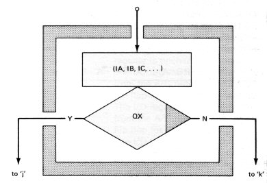
The highly parallel, microprogrammed state machine in the HP 9100A made the calculator very fast relative to competing machines. That was Tom Osborne’s original intent when he’d designed the Green Machine. However, Osborne’s design approach also had unintended consequences. The first consequence was the way in which the firmware for the HP 9100A was written. There were no programming tools for the machine because there wasn’t really a processor in the classical sense. The HP 9100’s processor was a microprogrammed state machine that had no instruction set and no fetch/execute cycle. Thus there was no assembler, compiler, or linker. The state machine was programmed using graphical flow charts, which Osborne himself then hand translated into state-machine ROM code (essentially ones and zeroes).
Firmware programming for the calculator operations was done primarily by Dave Cochran, who had worked with Chuck Near previously on the very successful HP 3440A digital voltmeter. Cochran was drafted for the position of the HP 9100A project’s state-machine programmer, something any universal HP engineer would be expected to do even if he knew nothing about programming, which Cochran didn’t. In fact, he got the job in classic military style. During the initial meeting when development tasks were being parceled out to HP Labs engineers, Barney Oliver said, “We’ll need someone to work on the algorithms.” Cochran piped up and asked, “What’s an algorithm?” thus ensuring that he would get the job. Among the things he learned was that the word “algorithm” was named after the great Arab mathematician Mohammed ibn-Musa al-Khowarizmi, who taught in Baghdad sometime between 800 and 850 AD and developed algebra. Cochran also learned that algorithm development and programming are lonely jobs and have been for more than 1000 years.
Cochran started out by analyzing algorithms in general and Volder’s CORDIC algorithms specifically. Macmillan explained Volder’s algorithms mostly by referring Cochran to Volder’s papers so Cochran flew down to Costa Mesa, California one day to talk directly to Volder. Volder explained his own algorithms and also pointed Cochran to other important algorithms including some pseudo multiplication and pseudo division algorithms published by J. E. Meggitt in the IBM Journal in 1962. Mostly, Cochran was on his own.
Because Volder had developed his algorithms for terrestrial navigation of the supersonic Hustler bomber, his original algorithms were implemented in fixed point and had limited accuracy, which was all the bomber needed to hit its target or to find its home base and land. Cochran extended the accuracy of Volder’s algorithms to match the HP 9100’s wide floating-point numeric range. He had to make all of the algorithms fit into the HP 9100’s very small ROM. It would have been a tough job for an experienced programmer and Cochran had no programming experience, but he was an HP engineer molded in the original style and he persevered.
Cochran learned to program computers during this period so that he could test his algorithms long before the HP 9100A hardware was operational. He programmed trial algorithms using a timeshared Burroughs B5500 mainframe located at Stanford. He worked to find simple, elegant, and accurate ways to compute all of the planned functions because ROM space was extremely limited. Over a period of six months, Cochran managed to shoehorn all of the HP 9100A’s arithmetic and functional routines, with at least 10 digits of accuracy, into the paltry 512 words of the HP 9100A’s ROM through a lot of hard work involving the use of intensive subroutine nesting and by developing a number of other space-saving programming tricks. For example, he made liberal use of natural logarithms (which the HP 9100 had to calculate anyway) to substitute multiplication and division for addition and subtraction. This approach saved ROM space and sped the calculations. In the final machine, Cochran used Volder’s CORDIC algorithms to calculate trig functions; Meggitt’s algorithms for pseudo multiplication and pseudo division to calculate logarithms, exponentials, and square root functions; and well-known math identities to compute hyperbolic functions.
Today, professional programmers should recoil at the thought of such tightly knotted code, which usually cannot be maintained. But in the late 1960s, Cochran had no choice but to throw every programming trick he could find or think up at the code because no more memory would fit into the machine and Osborne’s VLIW processor was at its limit in terms of address space. Cochran’s programming acumen garnered high praise from Barney Oliver, who called the development of the HP 9100A ROM code a “remarkable job,” which is high praise indeed from a guy known to be a very tough boss. After the HP 9100 project, Cochran would manage the work on HP’s most famous calculator, the groundbreaking HP 35 pocket scientific calculator, and several subsequent pocket calculators. His work on algorithms would serve him well on these future projects.
Because the HP 9100A used a highly parallel state machine to control all of its operations, several tasks executed simultaneously. While Cochran’s code was performing computations using one portion of the HP 9100’s state machine, another part of the state machine was busy refreshing the 3-line CRT display. The display code was written by Tony Lukes, who also wrote the HP 9100A’s program editing, storage, and execution firmware.
An evolutionary dead end
The tightly knotted and highly optimized design of the HP 9100A’s hardware and firmware led to a second architectural consequence. HP unveiled the HP 9100A in September, 1968 and the double-memory version (the HP 9100B) about one year later. But when it came time to develop the next-generation desktop calculators around 1970, the HP 9100A’s highly refined, streamlined, and microprogrammed architecture proved effectively unexpandable.
Although the IC technology circa 1970 could readily replicate the logic used in the existing HP 9100A and B calculators, the calculator’s VLIW processor architecture (including the address range of the program (next-state) counter and register-addressing capacity) was too limited to accommodate the bigger programs HP’s calculator users wanted to create. Osborne’s design could not easily be expanded without slicing Cochran’s Gordian knot—his tightly nested, hand-coded firmware—to ribbons. In addition, as mentioned earlier, there were no software-development tools for the HP 9100A’s one-of-a-kind processor so a code rewrite would have been extremely difficult.
Further, the HP 9100A’s 6-bit data-memory word had quickly become dated in a computing world that increasingly used 8-bit memories and communicated using 7-bit ASCII code. Even IBM had switched to 8-bit character storage in its System/360 mainframes. Thus HP’s next-generation desktop-calculator architects abandoned the HP 9100A’s fast, elegant design and elected to use an entirely different architectural approach. Although the hardware design of Tom Osborne’s brainchild became an evolutionary dead end for HP’s desktop calculators, HP would build two more desktop calculator generations that closely emulated the friendly operation and easy user programmability developed for the HP 9100A, even though the underlying hardware in those newer machines was radically different in each subsequent generation. Further, HP would continue to build handheld RPN calculators based on Osborne’s concepts for three decades.
Cast aluminum beauty
The HP 9100A differed from its successors in another significant way. Its futuristic design was considered quite beautiful and it was intentionally built like a tank. HP spent a bundle on the HP 9100A’s sleek industrial design and on the tooling for the calculator’s die-cast aluminum case. The key reason for these expenditures was because Bill Hewlett, who was intimately involved in this project starting from the day he poked his finger through the Green Machine’s balsa-wood case, was an engineering aesthete. He wanted HP equipment to work well and look even better. For Hewlett to be satisfied, even the insides of HP equipment had to look good.
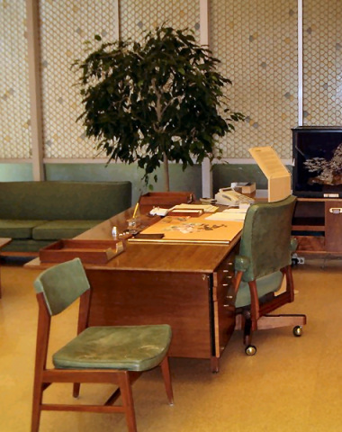
Hewlett wanted the HP 9100A to look good and he wanted it to be small. In fact, he required that the HP 9100 be small enough to fit on a pull-out typing stand built into his wooden work desk so that he could lower the stand and hide the calculator away inside the desk when not in use. It’s more than a little ironic that the form factor of this extremely complex and advanced piece of electronic computing equipment was to be determined by an old piece office furniture designed to support a typewriter—a 19th-century piece of office equipment.
In fact, the HP 9100A prototype fit on the typing stand but didn’t quite stow away inside the desk; it was just a bit too big. What happened next was an exercise in pure HP-style problem solving. The HP 9100A project engineers secretly had the company carpenter enlarge the opening in the desk just enough (about 1/8 of an inch) so that Hewlett’s size mandate was met. Dave Cochran, who told this story, recalls that Hewlett indeed never noticed the subterfuge (or at least never mentioned that he’d noticed).
Immediately after An Wang’s visit to see the production prototype calculators at Electro in 1968, Hewlett told Osborne that the next machine would need to be ten times smaller, ten times cheaper, and ten times faster. With those words, Hewlett ordered the eventual creation of the machine that would become the HP 35 pocket scientific calculator. Because Hewlett wanted that new calculator to fit in his shirt pocket, Cochran quips “We thought for a while we’d have to get a hold of his tailor.” It would take three more years before semiconductor technology could catch up to Hewlett’s vision of a pocket scientific calculator.
Not for the weak of heart
Nowhere in the HP 9100A’s design is its curtailed architectural future more readily apparent than in the machine’s I/O abilities. Put bluntly, the original HP 9100A architecture was not really designed to interface to any external equipment. It was designed to be a calculator that strictly interacted with human operators. Although the production model did sport a rear-mounted interface connector, the signals on that connector merely reflected what was already happening inside of the machine and were really intended for testing the production units.
Consequently, interfacing to the HP 9100A was not for the weak of heart. Tom Osborne, the machine’s own creator, described it this way:
“The signals emanating from its [the HP 9100’s] I/O connector were fondly referred to as ‘semi-modulated white lightning.’ The peripherals that connected to the I/O connector stand as a tribute to engineering. The obstreperous nature of the HP 9100A I/O was a strong contributor to the fact that its descendants have excellent I/O characteristics.”
Essentially, the HP 9100A’s I/O connector carried the raw, serialized BCD display data being sent internally to the calculator’s CRT display along with the encoded information that Cochran had tucked into the read/write core memory’s available nooks and crannies. Thus output operations consisted of loading specific values into the visible X, Y, and Z registers so that these values would appear on the display and would therefore also appear on the calculator’s I/O connector. Any peripheral connected to the HP 9100A had to interpret those signals and then determine what to do with the resulting information. The HP 9100A provided no help in assigning meaning to the numbers stored in its X, Y, and Z registers.
The calculator’s interface connector also offered a 6-bit keycode-input port with control inputs that allowed peripheral devices to disable the calculator’s physical keyboard and to jam data into the calculator’s keyboard buffer (the X register). Input operations therefore consisted of the peripheral device disabling the calculator’s keyboard and then entering keycodes from the back connector. Because the entire calculator was a giant state machine under total control of its keyboard, this approach to I/O was the only reasonable one to take because it didn’t require any substantial changes to the HP 9100’s design and, most important, required no additions to Cochran’s firmware. The calculator didn’t care if the keycode sequences came from its real keyboard or from a virtual keyboard attached to its I/O connector. Both initiated the same state-machine sequences.
For example, the HP 9120A electrostatic printer could print the contents of the HP 9100A’s X, Y, and Z registers and could print program listings. The X, Y, and Z register contents were constantly cycling on the I/O connector, digit by digit, so accessing these values was merely a matter of synchronization and capture. (Similarly, operation of the HP 9125A plotter also depended on the calculator’s displayed X and Y registers. The X and Y registers were used as a coordinate pair that told the plotter where to move its pen.)
To get a program listing, the printer disabled the HP 9100A’s keyboard, put the calculator in program mode so that the display would show the program steps stored in the calculator’s registers, and then stepped through the program so that the keycode values for the program steps sequentially appeared in the HP 9100A’s display and on the interface connector’s output pins.
A big memory for the HP 9100A
Perhaps the most complex HP 9100A and HP 9100B peripheral was the HP 9101A Extended Memory. This external box added 20,832 bits of core memory to the calculator, organized as 248 registers and capable of storing 3472 program steps. The HP 9101A Extended Memory’s registers could not be used like the calculator’s internal registers because they were located on the other side of the calculator’s I/O bus. So access time was much slower. In addition, the calculator lacked direct addressing capability for the additional registers because the expanded memory had not been considered during the HP 9100A’s initial design.
Consequently, the HP 9101A project engineers developed an ingenious indirect addressing scheme for accessing the HP 9101A’s 248 registers that fit into the calculator’s existing design. This addressing scheme used the calculator’s X register as an indirect pointer into the HP 9101A’s extended-memory register array and it used the Y register to hold operands. The calculator (under control of the HP 9101A) could either move data back and forth between its Y register and the designated extended-memory register or it could perform indirect arithmetic directly on the contents of the designated extended-memory register. For example, it could add the value held in the Y register to the contents of the designated extended-memory register and then store the result back into the same extended-memory register. These operations were actually performed by the HP 9101A and not the calculator, but the operator couldn’t tell the difference.
The HP 9100A and HP 9100B calculators could also use the HP 9101A extended memory to store programs by copying them from the HP 9100A internal registers to the HP 9101A’s registers. However, the HP 9100A could not directly execute programs stored in the HP 9101A. These externally stored programs first had to be loaded into the calculator’s internal registers from the HP 9101A using an appropriate key sequence. Loading a new program overlaid any existing programs or data in the calculator’s internal registers. Consequently, this feature led to the development of a variety of increasingly sophisticated HP 9100A programming techniques—including program overlays, subroutines, and subprograms—that greatly enhanced the calculator’s programmability.
Even with its rudimentary approach to I/O, HP’s engineers were able to produce an impressively large series of compatible peripheral devices for the HP 9100A including the following:
- HP 9101A extended memory, which added 248 registers capable of storing 3472 additional program steps
- HP 9102A calculator buffer, which “expanded” the one calculator I/O slot to two, allowing the calculator to have multiple peripherals. HP 9102A buffers could be daisy chained to allow the connection of multiple peripherals
- HP 9106A typewriter coupler
- HP 9107A digitizer
- HP 9120A electrostatic printer
- HP 9125A XY plotter
- HP 9150A display monitor, a large-screen CRT display for use in classrooms or with other large groups
- HP 9160A optical (mark/sense) card reader
In fact, the large number of compatible peripherals prompted HP to start referring to the collection of HP 9100 products as the “System 9100.”
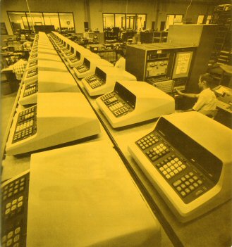
How the HP 9100A moved to Colorado
It’s not sufficient to develop a machine like the HP 9100A. The entire manufacturing flow must also be developed. For that to happen, the HP 9100A had to have a home. Oliver’s HP Labs had to find a manufacturing division willing to take the calculator on as a new product. As the only HP division building large, complex digital products, the logical home for this machine was the new minicomputer division located in Cupertino. However, the HP 9100A didn’t look, taste, or smell like a “real” computer and Cupertino wouldn’t touch it.
Fortunately, Marco Negrete, the R&D lab manager at HP’s Loveland Division in Colorado, would. He brought the HP 9100A into Loveland under Bob Watson in engineering and Jack Anderson in production. He also finally convinced Chuck Near to move to Colorado, something he’d been trying to do since Near and Cochran developed the HP 3440A digital voltmeter in the early 1960s. Near had been involved with the HP 9100 project from the start and he had devoted a lot of time to developing automated production tests based on the HP 2116 minicomputer for HP 9100A components, including the 32-kbit ROM board. This time, Negrete really needed Near.
Negrete was eager to take on new products like the HP 9100 in profitable new markets because he was not satisfied with the voltmeter, signal generator, and power supply product lines Loveland currently made. Although these existing product lines were solid revenue makers, they no longer constituted high-growth opportunities.
Negrete suspected that desktop computation might just be such a high-growth arena. He was right. The HP 9100A was so successful that it spawned a new division (the Calculator Products Division, which spun out of and was co-located with the Loveland Division). Eventually, the Calculator Products Division became the Desktop Computer Division and grew so large and successful that it moved up the road to Fort Collins, Colorado and into its own facility.
|

|
|
Logo for HP’s Desktop Computer Division (DCD)
Image courtesy of Fred Wenninger
|
|
Digital-interface Babel
While the HP 9100A calculator was moving from HP Labs in Palo Alto to the Loveland Division, HP was starting to feel pain (or at least substantial discomfort) from the broad incompatibility of the various digital interfaces incorporated into the company’s rapidly expanding line of minicomputers, desktop calculators, peripherals, and instrumentation products. Voltmeters and counters had one type of interface (usually BCD), programmable power supplies had another, computers had 8-bit or 16-bit unidirectional or bidirectional digital interfaces, printers employed a variety of different interfaces, and so on.
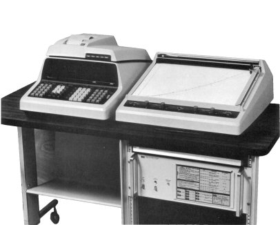
An early HP solution to this digital-interface Babel was the Model 2570A Coupler/Controller. The Coupler/Controller’s “2500” product-line series designation identifies it as a product of HP’s Dymec Division in Palo Alto. One of the reasons HP had created Dymec in the mid 1950s was to build integrated test and measurement systems based on HP products. Part of Dymec’s evolving charter was to create new instrumentation products when needed to aid in the development of those test systems. The HP 2570A Coupler/Controller was one of those products. However, the HP 2570A did not originate at Dymec. It grew out of a project started at the Loveland Division by Geoff Chance.
|
|
|
Geoff Chance
Photo courtesy
Hewlett-Packard Company
|
|
|
|
|
|
Fred Wenninger
Photo courtesy Hewlett-Packard Company
|
|
|
|
Geoff Chance Remembers the
Synchro-Rectro-Flash (SRF)
and Fred Wenninger
The analog computer was Fred: Magnum. Bold. Risky. Smoke and Mirrors. I and the troops would follow him over the white cliffs. Win big, lose big.
When the SRF was canceled, it was moved to the fan room on the west end of the mezzanine of HP building 1 in Loveland. As came with killing of projects, there was a lot of animosity. Someone cruelly taped the following to the face of old SRF:
This monstrosity stands
as a monument for mankind
[of a failure of leadership]
and the folly of human endeavor.
The words in brackets are my recollection/paraphrase of what was on the note, the rest are close to verbatim.
The SRF cost Loveland $2M. If it would have continued to production, it would have cost at least $5M more, as all we had was a $2M breadboard. Fortunately, the 9100A was about to change the world.
One weekend, Fred Wenninger came in and snuck the beast out to it's resting place. That is where it should remain: buried and faced towards Loveland, with a few words said, the playing of Taps from afar, followed by a big party for Fred and the SRF.
Great memories of another time,
Geoff
|
|

|
|
The Synchro-Rectro-Flash remained in Fred Wenninger’s barn for 30 years. Photo courtesy of Marl Godfrey.
|
|
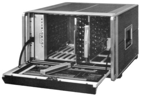
The Synchro-Rectro-Flash
Geoff Chance had joined Fred Wenninger’s R&D group in HP’s Loveland Division in June, 1965 (about the same time that Tom Osborne made his fateful first visit to Barney Oliver and Paul Stoft at HP in Palo Alto). Wenninger’s group in Loveland was working on an analog computer, dubbed the “Synchro-Rectro-Flash,” which was a huge piece of equipment about four feet wide, two feet deep, and 3 ½ feet tall. Wenninger had written his doctoral dissertation on the solution of non-linear equations using an analog computer and it’s likely that he was the only person in the world who would truly understand how to use the Synchro-Rectro-Flash. Further, the analog computer was loaded with unreliable op amps that gave it a mean time to failure of about one hour, making it a most cantankerous beast.
The Loveland Division spent a lot of R&D money and two years on the analog computer’s development. Unfortunately, the rest of the world increasingly went digital during those two years. For example, during those critical years, HP developed both the HP 2116A minicomputer and the HP 9100A desktop calculator. Both were sophisticated digital machines. Loveland’s analog computer project did not reach production and was eventually shelved (or closeted) because of the development costs and the machine’s continued lack of reliability. The prototype machine’s carcass hung around in a closet in the Loveland plant for many years. Finally, Fred Wenninger spirited it away one weekend and stashed it in a barn on his farm in Ft. Morgan, Colorado, where it remained for 30 years.
After the demise of the Synchro-Rectro-Flash project, Chance remained in Wenninger’s downsized R&D group but started looking for something else to work on. During the analog computer project, he had interfaced a Teletype to the analog computer, thus establishing himself as a lone digital guru amongst the mostly analog-centric power-supply, signal-generator, and voltmeter engineers working at Loveland Division. In casting about for something new to do, Chance started to apply his interfacing experience to other problems. One problem he addressed was getting the HP 9100A’s complicated interface bus to communicate with more than just its own peripherals. Significantly, the HP 9100A was in the process of moving from HP Labs to the Loveland Division, which manufactured many instrument products that could greatly benefit from direct calculator control.
There was no interfacing standard for instruments in 1967 so different HP instruments and peripherals sported many different interfaces. For example, digital voltmeters like the HP 3440A had parallel BCD output connectors and separate, parallel, digital input connectors for control signals. Controllable power supplies also had multiple control terminals, but these terminals did not accept digital programming signals. They were analog terminals. When connected in various combinations through switches or relays, these terminals connected various circuit nodes inside of the power supply and thus programmed the power supply’s outputs.
In addition, the introduction of the HP 2116 instrumentation minicomputer had caused HP to OEM (purchase and rebrand for resale) a variety of computer peripherals such as paper-tape readers and punches and Teletype teleprinters. These peripheral devices would also be useful in systems based on the HP 9100A if the problem of their incompatible interfaces could be overcome.
The HP 2116A minicomputer dealt with the variety of peripheral interfaces by employing a different I/O card for each type of interface. HP 2116A interface cards included the:
- HP 12551B relay output register, for programming controlled power supplies.
- HP 12554A 16-bit duplex register.
- HP 12555A digital-to-analog converter, for driving oscilloscopes, strip-chart recorders, and analog X-Y plotters.
- HP 12556B 40-bit output register, used primarily for driving HP’s 5050B and 562A numeric strip printers, which had parallel BCD inputs designed to be driven by the parallel BCD outputs on digital voltmeters.
- HP 11597A 8-bit duplex register.
The HP 2116A minicomputer had a large card cage with enough I/O slots (available through an expansion chassis) to accommodate as many as 48 interface cards. The derivative HP 2115A minicomputer was limited to 40 interface cards. The HP 9100A desktop calculator had only a single interface connector plus its buffer box, which added just one interface connector per buffer box.
The Link
Chance teamed with Bob Tinnen, another alumnus of Wenninger’s defunct Synchro-Rectro-Flash project, to develop an external box that greatly expanded the HP 9100A’s interfacing abilities beyond its one-slot limitation. This box became known internally as “The Link.”
Like the HP 2116A’s I/O-card cage, The Link accepted multiple interface cards. Each card implemented a different instrument or peripheral interface and used a common bus protocol to communicate with other cards in The Link’s card cage using an 8-bit, multi-master bus embedded in The Link’s backplane. The Link’s internal bus also included control lines named “I have control,” “I am busy,” and “I want control” that allowed the various interface cards to pass control of the bus back and forth.
Chance and Tinnen developed a few prototype interface cards for The Link including one that interfaced to the yet-to-be-introduced HP 9100A calculator and another that interfaced to digital voltmeters. Using these two cards plugged into The Link, an HP 9100A could accept and process readings from a digital voltmeter. A summer intern named Alan Richards (who subsequently earned an engineering degree and joined HP in Loveland) developed a Teletype interface card. Chance and Tinnen then demonstrated The Link to Hewlett, Packard, and other HP division managers during a division review. (In the 1960s and even into the 1970s, Hewlett and Packard still made the time to regularly visit each of the company’s divisions to review ongoing operations and R&D projects. They were very hands-on corporate managers and they took their division managers with them during these reviews to make sure that the knowledge of the company’s ongoing developments spread throughout the company. Eventually, Hewlett-Packard grew too big to support this management style.)
The Dymec Division manager either saw or heard about Chance’s demonstration of The Link and objected, claiming his division’s turf was being violated. After some amount of corporate political wrangling, The Link’s ongoing development shifted to Dymec in California and Chance spent some time in Palo Alto to effect the move. The Link evolved, grew, improved, and changed shape at Dymec. More interface card types were developed and the product was introduced in 1970 as the HP 2570A Coupler/Controller. (By that time, Dymec itself had evolved into the Automatic Measurement Division.)
R&D engineers at the Automatic Measurement Division developed several cards for the HP 2570A, with features that closely resembled (and possibly borrowed circuitry from) the interface cards developed for the HP 2116A minicomputer. These HP 2570A interface cards connected to a variety of HP equipment and included the:
- HP 12802A Calculator card—interfaced to the HP 9100A and HP 9100B desktop calculators. This card translated between the calculator’s 4-bit BCD data (5 bits with a sign bit) and 6-bit keycodes and ASCII and allowed the calculators to control multiple instruments in the same system.
- HP 12797A BCD input card—interfaced to digital voltmeters and counters.
- HP 12798B BCD output/40-bit output card—interfaced to digital recorders, frequency synthesizer programmers, digital voltmeters, programmable voltage sources, and frequency counters.
- HP 12799B 16-bit relay register card—programmed power supplies and controlled actuators such as valves and solenoids.
- HP 12800A 8-bit duplex register card—interfaced to paper tape readers and punches and to HP 2100-series computers with 8-bit interfaces.
- HP 12801A teleprinter interface card—interfaced to electromechanical teleprinters (what you called a Teletype if it wasn’t made by Teletype) using a serial, current-loop interface.
- HP 12803A 10-channel reed-relay scanner—multiplexed analog signals so that one digital voltmeter could take several automatic measurements.
- HP 12809B time-sharing interface—a serial (RS-232) interface for connecting to modems and acoustic couplers.
- HP 12811A clock/timer/pacer card—adds flexible and accurate time-measurement capabilities to the HP 2570A coupler/controller.
- HP 12770A serial data communications interface—provides a serial interface between the HP 2570A coupler/controller and HP 2100-series minicomputers with a range of 10,000 feet.
The project leader for the HP 2570A at HP’s Automatic Measurement Division was Gibson (Gib) Anderson. In his 1970 HP Journal article on the HP 2570A, Anderson nicely summarized the concept behind the product:
“If computers, instruments, and peripherals could speak, and if they all spoke the same language, there would be few interface problems. Computers could tell instruments what to do, and the instruments would respond with data. … Since this isn’t the way things are, interface problems have to be solved either by special hardware, which can be expensive, or by human beings, who have better things to do than take long lists of readings and laboriously key the data into a calculator or time-sharing terminal.”
The HP 2570A hardware consisted of little more than an 8-slot card cage and power supply. Its real, lasting contribution was that of a common interface standard for a multi-master communications protocol based on ASCII. In a few years, the HP interface bus—HPIB, also called GPIB or IEEE-488, and also developed in Loveland—would accomplish the same goal but at a much lower cost. HPIB would spread throughout HP like wildfire and it was the spark that triggered the creation of another very successful instrumentation company: National Instruments of Austin, Texas.
Even though the HP 9100A desktop calculator was not specifically designed to interface to other equipment, the large number of peripherals developed by HP for the calculator plus the interfacing abilities of the HP 2570A Coupler/Controller overcame the calculator’s built-in I/O limitation and created the expectation that future HP calculators would be even more adept at controlling HP instruments and peripherals. This expectation directly resulted in the expanded I/O abilities built into all future generations of HP’s desktop calculators and computers. Meanwhile, the HP 2570A evolved into a long-lived series of successful HP/Agilent test and measurement products called multiprogrammers.
A standing ovation
Chance returned from Palo Alto to the Loveland Division and continued work on the HP 9100A. Shortly before its announcement in September, 1968, Chance and Jack Dunn, HP Loveland’s Marketing Manager, took a pre-production HP 9100A and an HP 9125A plotter to the Jet Propulsion Laboratory in Pasadena, California. As Chance explains, “It was a significant historic moment.” The System 9100 pumped out complex Bessel-function antenna patterns on the plotter and the JPL audience stood up and cheered. This demonstration of the HP 9100’s ability to excite the scientific and engineering community was an early indicator that HP really had developed a significant new product category.
Many people first learned about computers from their HP 9100A experiences. At least three famous people have interesting HP 9100A stories. The first is the story of Apple’s Steve Jobs. The HP 9100A was the first small computer Jobs saw and he “fell in love with it.” He realized that personal computing had the power to change people’s lives. Then he built a company to produce machines to do just that.
Author Arthur C. Clarke, who crafted one of the most infamous fictitious computers ever, the HAL 9000 in 2001: A Space Odyssey, was extremely impressed with the HP 9100A and mentioned that he’d like to have one. Barney Oliver presented an HP 9100A to Clarke in April, 1970. Clarke dubbed the machine HAL, Jr.
Finally, Dr. James van Allen, space scientist and professor emeritus at the University of Iowa, used an HP 9100A and the HP 9125A plotter to study the feasibility of using a gravity slingshot around Jupiter to allow Pioneer 11 to intercept Saturn. Pioneer 11 was retasked en route and arrived at Saturn before Voyager 1. Pioneer 11 is now leaving the solar system, heading towards the stars.
There are doubtless many such stories associated with the HP 9100A. The machine was so successful that it sparked the creation of a new HP division, paved the way for more powerful desktop machines, and allowed HP to command the desktop calculator and computer markets for more than a decade until just after IBM introduced the IBM PC in 1981 and ended the party.
References
This Web page is based on the personal recollections of Tom Osborne, Chuck Near, David Cochran, Geoff Chance, and Jim Williams and on the following articles, books, and Web sites:
Jack Volder, “The CORDIC Computing Technique,” 1959 Proceedings of the Western Joint Computer Conference, March 3-5, 1959, p 257-261.
Jack Volder, “The CORDIC Trigonometric Computing Technique,” IRE Transactions on Electronic Computers, September, 1959, p 330-334.
J. E. Meggitt, “Pseudo Division and Pseudo Multiplication Processes,” IBM Journal, April 1962, p 210-226.
Jack E. Volder, “The Birth of CORDIC,” Journal of VLSI Signal Processing 25, 2000, p 101-105.
John Stephen Walther, “The Story of Unified CORDIC,” Journal of VLSI Signal Processing 25, 2000, p 107-112.
Richard E. Monnier, “A New Electronic Calculator with Computerlike Capabilities,” HP Journal, September, 1968, p 3-9.
Thomas E. Osborne, “Hardware Design of the Model 9100A Calculator,” HP Journal, September, 1968, p 10-13.
David S. Cochran, “Internal Programming of the 9100A Calculator,” HP Journal, September, 1968, p 10-13.
Charles W. Near, “Computer-Testing the Model 9100A Calculator,” HP Journal, September, 1968, p 10-13.
Bernard M. Oliver, “How the Model 9100A Was Developed,” HP Journal, September, 1968, back cover.
Charles W. Near and Robert E. Watson, “Read-only memory adds to calculator’s repertoire,” Electronics, February 3, 1969, p 70-77.
A Pocket Guide to Interfacing HP Computers, Hewlett-Packard Company, April, 1970.
A Pocket Guide to Hewlett-Packard Computers, Hewlett-Packard Company, date unknown.
Gibson F. Anderson, “A Programmable, Modular, Bidirectional Data Coupler,” HP Journal, September, 1970, p 2-6.
Russell Sparks, “More Memory for Desktop Calculators,” HP Journal, October, 1970, p 2-7.
Gene Zeller, “Optical Card Reader for Fast Calculator Programming,” HP Journal, October, 1970, p 8-12.
Chuck McAfee, “Hard Copy Output For The System 9100 Computing Calculators,” HP Journal, October, 1970, p 13-16.
Paul Asmus, “Which Computer – The Programmable Calculator,” Electronics World, September, 1971.
Daniel P. Siewiorek, C. Gordon Bell, Allen Newell, Computer Structures: Principles and Examples, McGraw Hill, Inc., New York, 1982.
Daniel Morrow, “Excerpts from an Oral History Interview with Steve Jobs,” April 20, 1995, available at www.geocities.com/franktau/interviewpart1.html.
Kip Crosby, “A Core Plane in Amber: An Interview with Barney Oliver, Part One” The Analytical Engine, Journal of the Computer History Association of California, Volume 2, Number 3, May 1995, p 8-24.
Kenneth Jessen, How It All Began: Hewlett-Packard’s Loveland Facility, J. V. Publications, Loveland, Colorado, 1999.
Carolyn Said, “High-Tech Pioneer Hewlett Dies,” San Francisco Chronicle, January 13, 2001.
David Hicks, “HP 9100A/B,” The Museum of HP Calculators, http://www.hpmuseum.org/hp9100.htm and “HP 9100 Technology and Packaging,” http://www.hpmuseum.org/tech9100.htm
Heartfelt thanks to Dan Veeneman, Alex Knight, and Rick Bensene who have done wonderful jobs of documenting the HP 9100A and B desktop calculators on their Web sites: http://www.decodesystems.com/hp9100.html, http://hp.calcmuseum.com, and http://oldcalculatormuseum.com/hp9100b.html respectively.
|